Process Layout diagrams are created in the Admin Console. You must have access rights to the Admin Console to perform this task.
Create the Menu Item
- Go the Menus->Custom->Add New Menu item.
- On the Details tab, give the diagram a unique name.
- Using the Select button, open the Menu Items Types list, and select the Process Layout component under the Process Layout type. This will load the Process Layout component into the menu and create a Process Layout Settings tab for configuration of the diagram.
- On the right side of Menu page, be sure Custom menu is selected in the first drop down.
- Select Process Layout as the Parent Item for the new diagram: this will cause the new diagram to show up under Process Layout in the main menu. Alternatively,
- Optionally, on the Page Display tab of the menu item, use the Page Heading field to give the layout a title that will display on the page when the diagram is rendered.
- Save the Menu item.
- Go to the Process Layout tab to Configure the Process Layout.
Configure the Process Layout
Inside the Menu item for a Process Layout there is a tab for configuring the Process Layout parameters. After configuration, be sure to Save & Close the menu item. After creating or editing a Process Layout be sure to refresh the browser page to see the changes.
Initial Place
A plant is described in a hierarchical manner, starting with an Organization, which may be divided into one or more Places (think geographical locations, for example). Places can be divided into Areas, which are spaces or areas where a collection of equipment exists to perform a specific process in the manufacturing life-cycle. As such, Areas contain Equipment.
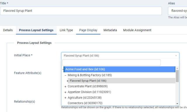
By selecting an Initial Place, you can create Process Layouts that particular place, e.g. plant-wide, a specific area, or a specific manufacturing line. The options that display in the Initial Place drop down are derived from the Physical Model of the plant.
Expand the tree to find the desired initial place; below, Flavored Syrup Plant is the Initial Place:
Feature Attribute(s)
Feature Attributes are the data that you would like to display on the Process Layout diagram. This data can be live data readings, calculated expressions such as power consumption, a static number such as capacity, or a state. The drop down list of attributes available for selection is filtered by the Initial Place.
Selecting Feature Attributes is optional.
Relationship(s)
The user has the option to select the relationship type(s) to be shown in a diagram of the Process Layout. For backward compatibility, all relationship types are shown if no relationship type is selected.
You select the relationship type(s) from the drop down list. The list is pre-filtered to relationship types that exists below the Initial Place. It is possible to select multiple relationships.
Only nodes that have the selected relationship type(s) (or any relationship type if none is selected) are shown in the Process Layout. If a node that belongs in the structure below the organizational root does not have the selected relationship type (either as a subject or object), then that node will not be shown in the process layout.
Network Root(s)
The drop down list of Network Roots is filtered by the Initial Place. You can select zero, one, or more Network Roots to display. Network Roots are pieces of equipment in the Physical Model that you want to concentrate on.
If (a) network root(s) is selected, then only nodes that are connected to this network root through the selected relationship type(s) will be displayed. An example of a network root is an electrical sub-meter that feeds motor control centers, which are feeding consumers of electrical power. All relationships in the Process Layout will originate from the network root. Nodes that don’t have a (single or multi-level) path back to the network root will not be displayed, even if they are below the organizational root and have the relationship type.
If no network root is selected, then all nodes that fulfill the requirements of the organizational root and the relationship type will be displayed.
Selecting Network Roots is optional.
Network Search Direction
The root search direction can be set to Forward or Reverse: if reversed, the root node is the object in the relationship. A use case for this is when you want to display all the equipment that feeds something to the root node (as a dependency diagram).
Miscellaneous
Refresh Interval, Min Name Length, Max Name Length, Min Value and Float Decimal Digits all have tooltips that describe their function.

